
 journal menu


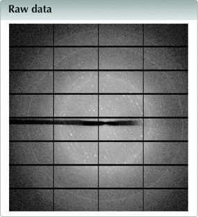
raw data letters
 | IUCrDATA |
 access
of the second extracellular domain of human tetraspanin CD9: and diffuse scattering

aDepartment of Chemistry, Structural Biochemistry, Bijvoet Centre for Biomolecular Research, Faculty of Science, Utrecht University, Utrecht, The Netherlands
*Correspondence e-mail: [email protected]
Remarkable features are reported in the diffraction pattern produced by a crystal of the second extracellular domain of tetraspanin CD9 (deemed CD9EC2), the structure of which has been described previously [Oosterheert et al. (2020![[Oosterheert, W., Xenaki, K. T., Neviani, V., Pos, W., Doulkeridou, S., Manshande, J., Pearce, N. M., Kroon-Batenburg, L. M. J., Lutz, M., van Bergen en Henegouwen, P. M. P. & Gros, P. (2020). Life Sci. Alliance, 3, e202000883.]](../../../../../../logos/arrows/iucrx_arr.gif "Oosterheert, W., Xenaki, K. T., Neviani, V., Pos, W., Doulkeridou, S., Manshande, J., Pearce, N. M., Kroon-Batenburg, L. M. J., Lutz, M., van Bergen en Henegouwen, P. M. P. & Gros, P. (2020). Life Sci. Alliance, 3, e202000883.") ), Life Sci. Alliance, 3, e202000883]. CD9EC2 crystallized in P1 and was twinned. Two types of diffuse streaks are observed. The stronger diffuse streaks are related to the twinning and occur in the direction perpendicular to the twinning interface. It is concluded that the twin domains scatter coherently as both Bragg reflections and diffuse streaks are seen. The weaker streaks along c* are unrelated to the but are caused by intermittent layers of related molecules. It is envisaged that the raw diffraction images could be very useful for methods developers trying to remove the diffuse scattering to extract accurate Bragg intensities or using it to model the effect of packing disorder on the molecular structure.
), Life Sci. Alliance, 3, e202000883]. CD9EC2 crystallized in P1 and was twinned. Two types of diffuse streaks are observed. The stronger diffuse streaks are related to the twinning and occur in the direction perpendicular to the twinning interface. It is concluded that the twin domains scatter coherently as both Bragg reflections and diffuse streaks are seen. The weaker streaks along c* are unrelated to the but are caused by intermittent layers of related molecules. It is envisaged that the raw diffraction images could be very useful for methods developers trying to remove the diffuse scattering to extract accurate Bragg intensities or using it to model the effect of packing disorder on the molecular structure.
Keywords: twinning; diffuse scattering; tetraspanin CD9EC2; raw data.
Metadata imgCIF file: https://doi.org/10.1107/S2414314622008525/he4557img.cif
Data processing and refinement
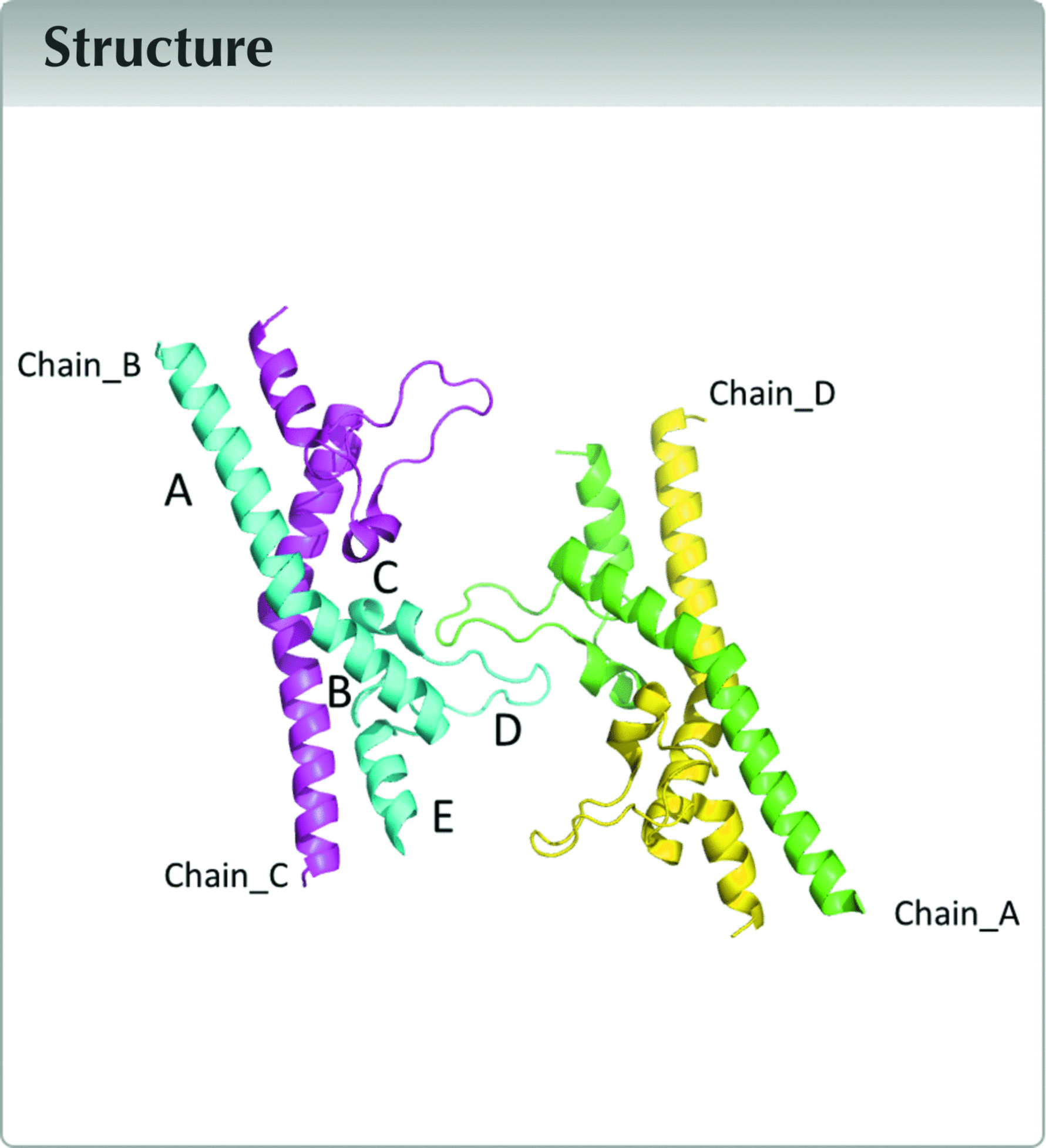
This letter gives a detailed description of the raw diffraction data that were used for analysis and of the second extracellular domain of tetraspanin CD9 (CD9EC2) as previously reported (Oosterheert et al., 2020). The raw diffraction images show streaked diffuse scattering, and this feature is detailed here to serve as an example for archiving and re-analysis of raw diffraction data. CD9EC2 crystallized in P1, has four molecules in the asymmetric unit, arranged as a dimer of domain-swapped dimers (Fig. 1). The crystal was non-merohedrally twinned with a twofold rotation about a* + b* as the operation.
![[Figure 1]](he4557fig1thm.gif) | Figure 1 Asymmetric unit of the twinned CD9EC2 crystal, coloured by protein chain. Domains are labelled A–E in the cyan-coloured chain. The D loop is flexible as follows from comparison of different structures involving CD9EC2 and structures of EC2 domains from other tetraspanins (Oosterheert et al., 2020 ). The direction of view is approximately along the non-crystallographic (NCS) twofold axis that coincides with the twofold twin axis a* + b* (see text). The NCS operation transforms chain A into chain B, and chain C into chain D. |
With the EVAL software suite (Schreurs et al., 2010) two lattices could be indexed and reflections of the largest domain were integrated while overlapping reflections of the second domain could be largely deconvoluted, leaving only 21.5% of reflections overlapping.
Initial de-twinning was performed with the TWINABS software (Sheldrick, 2009) based on observed structure factors. These data were used for structure solution by molecular replacement as described previously (Oosterheert et al., 2020). Final detwinning was based on calculated structure factors and final refinement rounds in Refmac5 yielded Rwork/Rfree = 23.9/27.9%.
Structural details can be found in (Oosterheert et al., 2020) and in the Protein Data Bank under the accession code 6rlr. Data collection details and statistics are listed in Table 1.
| ||||||||||||||||||||||||||||||||||||||||||||||||||||||||||||||||||||||||||
Data description
Data were collected at Diamond Light Source (DLS) beamline I-04, in total 3600 images in 0.1° fine sliced mode using a single rotation axis. The diffraction data were written in HDF5 format. Since, at the time of data processing, EVAL could not read the HDF5 files, they were converted by a tool at DLS to CBF format, using mini-cbf headers, and these were processed by EVAL. Both HDF5 (.h5) and CBF (.cbf) data files have been deposited in Zenodo. Indexing of peaks in the diffraction data with DIRAX (Duisenberg, 1992) indicated non-merohedral twinning of the crystal with a twofold rotation around the a* + b* diagonal as the (Fig. 2). Concurrent with twinning, diffuse streaks are seen in the diffraction. Diffraction images were mapped to reciprocal space, to a resolution of 4 Å, using IMG2HKL in EVAL (Schreurs et al., 2010), first by merging images in groups of 5, and then carefully redistributing intensities while correcting for Lorentz and polarization factors. The reciprocal space map was merged using Laue symmetry −1. The reciprocal space map is available as a CCP4 map (https://doi.org/10.5281/zenodo.6961763), that can e.g. be viewed with Chimera (Pettersen et al., 2004). Fig. 2(a) shows three sections through reciprocal space on an hkl grid, where evident streaks are running in the a* + b* direction, particularly in the hk2 section.
![[Figure 2]](he4557fig2thm.gif) | Figure 2 Twinned CD9EC2 crystal. (a) Reciprocal space reconstructions, hk0, hk2 and hk4. The lower panels are zoomed in at the area of the yellow box, where Bragg reflections originating from lattice 1 and 2 are coloured white and cyan, respectively. In slice hk2, streaks along a* + b* are evident. All slices hk(l = 4n) are ordered and the spots indexed by the two matrices nearly overlap, while in slices hk(l = 4n + 2) they have maximum separation. (b) Green and gold structures represent the two twin domains in the crystal. The second domain is rotated by 180° around a* + b* with respect to the first. The twin interface is the plane in the middle with base vectors c and a − b for either lattice. In the figure, molecules of the two domains are overlayed on this layer. The 180° twin rotation applied to domain 1 causes chains A and C of the molecules in domain 1 (green) to superimpose on chains B and D of domain 2 (gold), respectively. Starting from the interface the 4th layers (between the blue lines) in the two domains are the same and form an ordered array. A super cell (red) can be constructed with transformation matrix (1,−1,0/0,0,1/−2,−2,1) on which the two twin lattices overlap. The consequence is that in reflections of the twin lattices overlap for every l = 4n. |
In the following we draw conclusions on the origins of the diffuse scattering features we observed. A variety of diffuse scattering features in macromolecular crystals of different origin is discussed by Glover et al. (1991). For an extensive treatment of diffuse scattering in proteins, we refer to the paper on the Gag protein by Welberry et al. (2011). Geometrical frustration of the packing of two molecular configurations of the Gag protein led to circular diffuse scattering features. The origin of our diffuse scattering of CD9EC2, though, is different; we only have streaked diffuse scattering that is caused by stacking disorder of layers. We summarize here what we concluded in the Oosterheert paper on the origin of the diffuse scattering (see Fig. 2 for details).
The interface is a layer with base vector c and a − b. The two twin domains each grow from this interface along their respective a* + b* directions. For every fourth layer the two structures exactly overlap.
Reflections can be indexed on a so-called stacking lattice (Dornberger-Schiff, 1956; Lutz & Kroon-Batenburg, 2018) with dimension 1/4c. On this lattice the twin structure is completely ordered and as a result the reciprocal space slices at l = 4n have only ordered Bragg spots.
All the other slices have streaks in a* + b* which is the direction of the packing disorder.
A twofold NCS (non-crystallographic symmetry) operation transforms the independent molecules into one of the others; the corresponding axis co-aligns with twin axis a* + b*. Chain A superposes with chain B (r.m.s.d. 0.482 Å) and chain C with chain D (r.m.s.d. 0.460 Å). The CD9EC2 molecule has a flexible D loop (see Fig. 1, where the D loop is marked for chain B). In the structure this loop is located at the twin interface. A crystal consisting of small twin domains is coherently scattering over a length scale determined by the coherence length of the X-rays (see Thompson, 2017 for a discussion on order–disorder and twinning). This is the case for our crystal, which gives rise to both Bragg peaks and diffuse streaks [Fig. 2(a)].
It was noticed by a reviewer that streaks are also seen in the c* direction. This is indeed the case, and they occur for every hkl layer containing c*, but are significantly weaker than the a* + b* streaks [Fig. 3(a)]. The origin of the diffuse streaks lies within a single domain and is unrelated to the twinning. Our reasoning is that due to NCS, local rotation of molecules can occur, without serious clashes. It may be that within a single domain, a rotated copy of an entire ab layer is included in the lattice [see Fig. 3(b)], which is conceivable because the molecules are packed through the D loops. This leads to disruption of periodicity in stacking of ab layers and to diffuse streaks in the c* direction.
![[Figure 3]](he4557fig3thm.gif) | Figure 3 Diffuse scattering along c*. (a) Reciprocal space reconstruction of h0l layer and zoomed in at the area of the yellow box. Intensities are on the same scale as in Fig. 2 (a). Streaks are observed along c*, but much weaker than those along a* + b*. (b) Model of a single domain in which one layer is replaced by a rotation copy generated by the NCS rotation operation, which coincides with the twinning, i.e. 180° rotation around a* + b*. The colouring of the chains is the same as in Fig. 1, but the asymmetric unit used here (indicated by an ellipse) is such that the loops are on the outside. Inclusion of a layer of rotated copies will disrupt the periodicity perpendicular to the ab layer which is the c* direction, leading to diffuse streaks in the diffraction pattern. |
We present here the raw diffraction data and the most likely explanation for the diffuse features. Any interested researcher can generate detailed models of disorder, calculate the diffuse scattering and compare them with our data.
Supporting information
Link https://doi.org/10.5281/zenodo.5886687
HDF5 and CBF data files
Metadata imgCIF file. DOI: https://doi.org/10.1107/S2414314622008525/he4557img.cif
CheckCIF for raw data report. DOI: https://doi.org/10.1107/S2414314622008525/he4557img_check.pdf
References
 Dornberger-Schiff, K. (1956). Acta Cryst. 9, 593–601. CrossRef CAS IUCr Journals Web of Science Google Scholar
Duisenberg, A. J. M. (1992). J. Appl. Cryst. 25, 92–96. CrossRef CAS Web of Science IUCr Journals Google Scholar
Glover, I. D., Harris, G. W., Helliwell, J. R. & Moss, D. S. (1991). Acta Cryst. B47, 960–968. CrossRef CAS Web of Science IUCr Journals Google Scholar
Lutz, M. & Kroon-Batenburg, L. M. J. (2018). Croat. Chem. Acta, 91, 289–298. CSD CrossRef Google Scholar
Oosterheert, W., Xenaki, K. T., Neviani, V., Pos, W., Doulkeridou, S., Manshande, J., Pearce, N. M., Kroon-Batenburg, L. M. J., Lutz, M., van Bergen en Henegouwen, P. M. P. & Gros, P. (2020). Life Sci. Alliance, 3, e202000883. CrossRef PubMed Google Scholar
Pettersen, E. F., Goddard, T. D., Huang, C. C., Couch, G. S., Greenblatt, D. M., Meng, E. C. & Ferrin, T. E. (2004). J. Comput. Chem. 25, 1605–1612. Web of Science CrossRef PubMed CAS Google Scholar
Schreurs, A. M. M., Xian, X. & Kroon-Batenburg, L. M. J. (2010). J. Appl. Cryst. 43, 70–82. Web of Science CrossRef CAS IUCr Journals Google Scholar
Sheldrick, G. (2009). TWINABS. University of Göttingen, Germany. Google Scholar
Thompson, M. C. (2017). Identifying and Overcoming Crystal Pathologies: Disorder and Twinning, ch. 8, Protein Crystallography: Methods and Protocols in Methods in Molecular Biology, Vol. 1607. Clifton: Springer. Google Scholar
Welberry, T. R., Heerdegen, A. P., Goldstone, D. C. & Taylor, I. A. (2011). Acta Cryst. B67, 516–524. Web of Science CrossRef CAS IUCr Journals Google Scholar
This is an open-access article distributed under the terms of the Creative Commons Attribution (CC-BY) Licence, which permits unrestricted use, distribution, and reproduction in any medium, provided the original authors and source are cited.
| IUCrDATA |


